Synchronous state machine analysis
Not what you're looking for?
Please see the attachment.
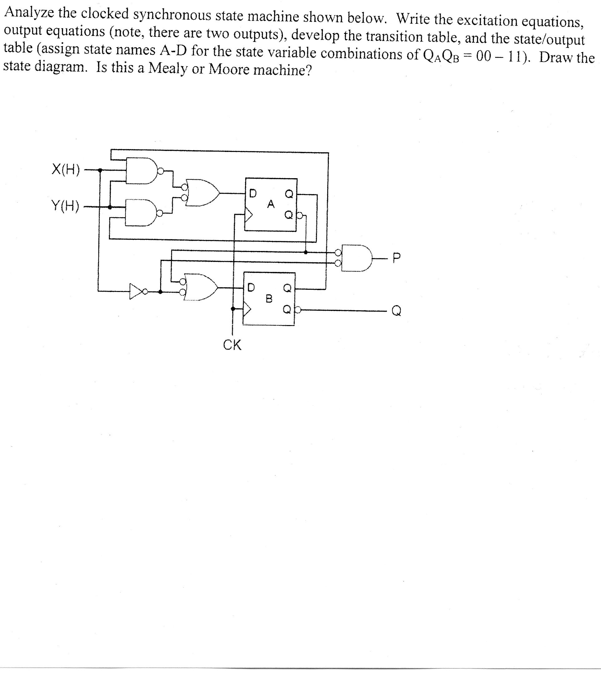
Analyze the clocked synchronous state machine shown in the file (part A). write the excitation and output equations. Develop the transition table and the state/output table. Draw the state diagram. Is this a Mealy of a Moore machine?
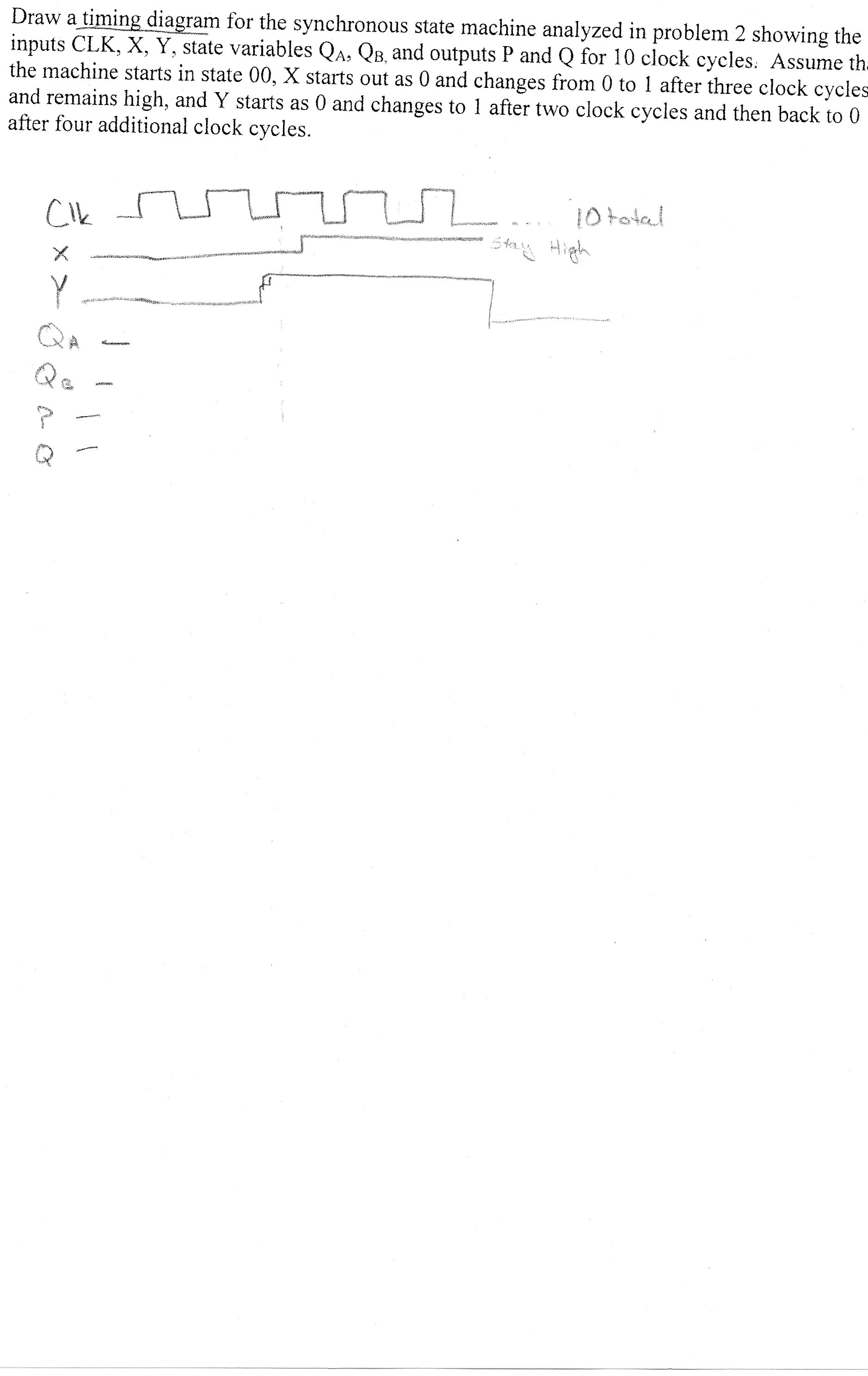
Draw the timing diagram for the machine for 10 clock cycles. assume the machine starts in state 00 X starts as 0 and changes to 1 after 3 clock cycles and remains high and Y starts as 0 and changes to 1 after two clock cycles and then back to zero after 4 clock cycles.
Purchase this Solution
Solution Summary
The 5-pages solution shows how to start with the circuit and analyze it all the way to the truth table and transition diagrams. It then analyzes the timing diagram.
Solution Preview
Please see the attachment.
Following the circuitry negating consecutive inverters, the functions of the flip-flop inputs and the outputs are:
The superscript NS refers to the next state of the system.
Since we are dealing with D Flip-Flops, the next state will be the input at the D gate.
Thus, the truth table is given in the next page:
Inputs Current state Next State Output
X Y QA QB DA DB P Q
0 0 0 0 0 0 0 1
0 0 0 1 0 0 0 1
0 0 1 0 0 1 0 0
0 0 1 1 0 1 0 0
0 1 0 0 0 0 0 1
0 1 0 1 0 0 0 1
0 1 1 0 1 1 0 0
0 1 1 1 1 1 0 0
1 0 0 0 0 1 0 0
1 0 0 1 0 1 0 0
1 0 1 0 0 1 0 0
1 0 1 1 0 1 0 0
1 1 0 0 0 1 0 0
1 1 0 1 1 1 1 0
1 1 1 0 1 1 1 0
1 1 1 1 1 1 1 0
If we ...
Purchase this Solution
Free BrainMass Quizzes
Architectural History
This quiz is intended to test the basics of History of Architecture- foundation for all architectural courses.
Air Pollution Control - Environmental Science
Working principle of ESP