Stiffness matrices and displacements in spring systems
Not what you're looking for?
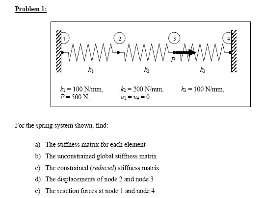
For the spring system shown in the attached diagram, find:
a) The stiffness matrix for each element
b) The unconstrained global stiffness matrix
c) The constrained (reduced) stiffness matrix
d) The displacements of node 2 and node 3
e) The reaction forces at node 1 and node 4
For the given spring system in the second attachment, find:
a) The stiffness matrix for each element (symbolically)
b) The unconstrained global stiffness matrix (symbolically)
c) The constrained (reduced) stiffness matrix (symbolically)
Take k1 = 100N/mm, k2 = 200N/mm, k3 = 300N/mm, k4 = 400 N/mm, P1 = 1000N, P3 = 3000N
d) The displacements of nodes 1, 2, 3 (numerically)
e) The reaction forces at node 4 and node 5 (numerically)
Purchase this Solution
Solution Summary
The solution calculates stiffness matrices for different elements of springs systems as well as displacements and reaction forces.
Solution Preview
Problem 1
a.) k1 -k1 100 -100
= (stiffness matrix for element 1)
- k1 k1 -100 100
k2 -k2 200 -200
= (stiffness matrix for element 2)
- k2 k2 -200 200
k3 -k3 100 -100
= (stiffness matrix for element 3)
- k3 k3 -100 100
b) k1 -k1 u1 f1ele1
X = (1)
- k1 k1 u2 f2ele1
k2 -k2 u2 f2ele2
X = (2)
- k2 k2 u3 f3ele2
k3 -k3 u3 f3ele3
X = (3)
- k3 k3 u4 f4ele3
P1= f1ele1 = k 1u 1-k1u 2 (4)
P2= f2ele1 + f2ele2 = - k1u1 +u2(k1 +k2) -k2u3 (5)
P3= f3ele2 + f3ele3 = - k2u2 +u3(k2 +k3) -k3u4 (6)
P4 = f4ele3 = k3u4 -k3u3 (7)
The above equations can be represented as
k1 -k1 0 0 u1 P1
- k1 k2 +k1 -k2 0 u2 P2
x = (8)
0 -k2 k2+k3 -k3 u3 P3
0 0 -k3 ...
Purchase this Solution
Free BrainMass Quizzes
Air Pollution Control - Environmental Science
Working principle of ESP
Architectural History
This quiz is intended to test the basics of History of Architecture- foundation for all architectural courses.