Circuit Diagrams, Pole Frequencies, and Bode Plots
Not what you're looking for?
Not exactly sure how to go about solving the attached problem - concepts include circuit diagrams, pole frequencies, and bode plots.
Purchase this Solution
Solution Summary
The circuit diagrams, pole frequencies and bode plots are examined in the solution.
Solution Preview
Please see the 2 attachments.
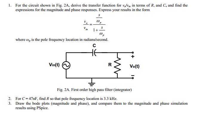
1. The first order high pass filter is shown below
Note that I have drawn this as 2 general impedances and as shown.
In this particular case since is a pure resistance we can say its impedance is simply
Similarly the impedance being a pure capacitance has an impedance given by where is the angular frequency of operation of the driving source and is the complex operator telling us that current and voltage are not in phase through such an impedance.
Moreover and to simplify the analysis we can substitute the parameter to obtain the impedance if we wanted to.
GENERAL TRANSFER FUNCTION EXPRESSION:
The output voltage is just given by the voltage divider rule for 2 impedances (in this case and in series) and taking the output voltage as over the impedance .We can therefore write the output voltage as measured across impedance using the voltage divider rule, thus
And as a result we can then write the transfer function as the ratio of to by re-arrangement of the above equation to get
Substituting in our impedance values derived earlier and we obtain
Multiplying top and bottom by (which doesn't change the value of the above as this is equivalent to multiplying by 1) we can write
Which when ...
Purchase this Solution
Free BrainMass Quizzes
Architectural History
This quiz is intended to test the basics of History of Architecture- foundation for all architectural courses.
Air Pollution Control - Environmental Science
Working principle of ESP