PLC and Circuit Diagrams
Not what you're looking for?
5
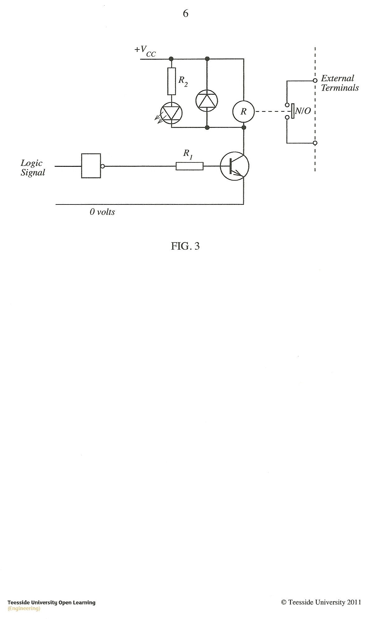
(d) The circuit shown in FIGURE 3 is part of the interface of a relay output module. Ib is 1 mA and Vcc is 9 V. The relay requires a minimum of 50 mA to energise.
Complete the values of the assumptions listed below in order to calculate:
• Voltage across R1 • value of Ri • voltage across the relay coil • voltage across R2 • value of R2 • collector of current
Assumptions:
Logic '1' = V Logic '0' = V
Transistor forward current gain h_i_e = LED current = 10 mA
LED voltage drop at 10 mA = V Base/emitter voltage = V Collector emitter voltage when transistor is on = 1 V
Purchase this Solution
Solution Summary
This posting contains the solution to the given problems.
Purchase this Solution
Free BrainMass Quizzes
Architectural History
This quiz is intended to test the basics of History of Architecture- foundation for all architectural courses.
Air Pollution Control - Environmental Science
Working principle of ESP