AC/DC BJT transisitor Circuit Analysis
Not what you're looking for?
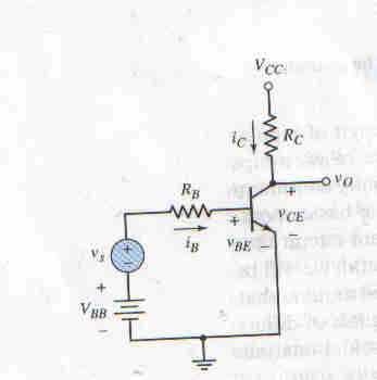
For the circuit in the image, Beta=120, VCC=5V, Va=100V, and Rb=25kohms. Determine Vbb and RC such that Rpi=5.4kOhms and the Q-point is in the center of the load line.
I have a formula for Rpi=(Vt*Beta)/Icq. From this I found Icq=1.25x10^-4 Amps.
However, is this a correct way to determine Icq? The question said to determine the values such that the Q-point is in the center of the load line. How do I draw the graph to find out the center value if I don't know Vce?
KVL around to ce loop relates RC and VCE: Rc=(5v-Vce)/(1.25x10^-4) if I can use the Icq from earlier.
Diagram is attached.
Please help. What am I missing? Thank you.
Purchase this Solution
Solution Summary
The solution provides aid and guidance to the problem concerning AC/DC BJT tansistor circuit analysis.
Solution Preview
Hi,
The way you got Icq is fine. But the value looks too small. Please check the unit just in case.
The ...
Purchase this Solution
Free BrainMass Quizzes
Classical Mechanics
This quiz is designed to test and improve your knowledge on Classical Mechanics.
Intro to the Physics Waves
Some short-answer questions involving the basic vocabulary of string, sound, and water waves.
Basic Physics
This quiz will test your knowledge about basic Physics.
Variables in Science Experiments
How well do you understand variables? Test your knowledge of independent (manipulated), dependent (responding), and controlled variables with this 10 question quiz.
Introduction to Nanotechnology/Nanomaterials
This quiz is for any area of science. Test yourself to see what knowledge of nanotechnology you have. This content will also make you familiar with basic concepts of nanotechnology.