Armstrong oscillator with secondary winding's
Not what you're looking for?
See the attached file.
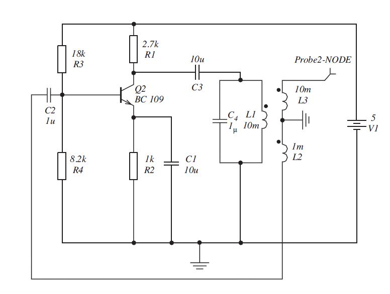
The figure attached shows the Armstrong oscillator. A transformer with two secondary winding's has been use, one to give feedback and one to give the oscillator's output. Write a short report [two to three pages] on an investigation into the operation and performance of this circuit 1.
The report should embrace, as far as you are able, the following themes:
(a) Why should the output be taken via the transformer rather than directly off
the collector of the transistor.
(b) Calculate quiescent voltages on the three terminals of the transistor.
(c) calculate the frequency of oscillation.
(d) The shape of the output waveform in the first 10 milliseconds of
start-up.
Purchase this Solution
Solution Summary
The solution discusses the Armstrong oscillator with secondary winding's.
Solution Preview
Please see attached for detailed solution.
Armstrong Oscillator Circuit operation summary:
• The DC analysis (Appendix 1) predicts the quiescent operating point which we call. This prediction indicates that the circuit will have a DC collector current of and a collector to emitter DC voltage. It also predicts the BC109 BJT terminal DC voltages to have the following; a DC collector voltage of, a DC base (bias) voltage and DC emitter voltage. These then form the starting point in the circuit analysis and form the basis of any description of the operation of the oscillator.
• A tank circuit can be seen to be present on the collector which is formed by the parallel combination of the primary coil (with inductance) and capacitance. This parallel combination determines the "ideal" frequency of oscillation for the circuit. In the real world slight loading effects due to any connected load and mutual inductances between primary and secondary coils will affect the centre frequency and its bandwidth slightly. The frequency analysis (Appendix 2) predicts the "ideal" frequency of operation to be
• To prevent any DC current flowing from the supply through to the collector tank circuit this tank circuit is coupled only to AC variations appearing at the collector via AC coupling capacitor.; this capacitor can also be alternatively viewed as providing a DC block to the tank circuit and collector terminal preventing any DC component of current flowing through the collector resistor .
• Secondary coil with an inductance, through the process of Faraday Induction, picks up a fraction of the voltage appearing across the primary coil. Coil is connected in reverse polarity to to ensure that produces a signal in anti-phase to that appearing across primary coil .
• Once connected to the supply, apart from the DC bias at the base, no signal exists at the input to the circuit (the base input). Any naturally occurring small AC noise signal at the ...
Purchase this Solution
Free BrainMass Quizzes
Basic Physics
This quiz will test your knowledge about basic Physics.
Variables in Science Experiments
How well do you understand variables? Test your knowledge of independent (manipulated), dependent (responding), and controlled variables with this 10 question quiz.
The Moon
Test your knowledge of moon phases and movement.
Introduction to Nanotechnology/Nanomaterials
This quiz is for any area of science. Test yourself to see what knowledge of nanotechnology you have. This content will also make you familiar with basic concepts of nanotechnology.
Intro to the Physics Waves
Some short-answer questions involving the basic vocabulary of string, sound, and water waves.