Power Factor
Not what you're looking for?
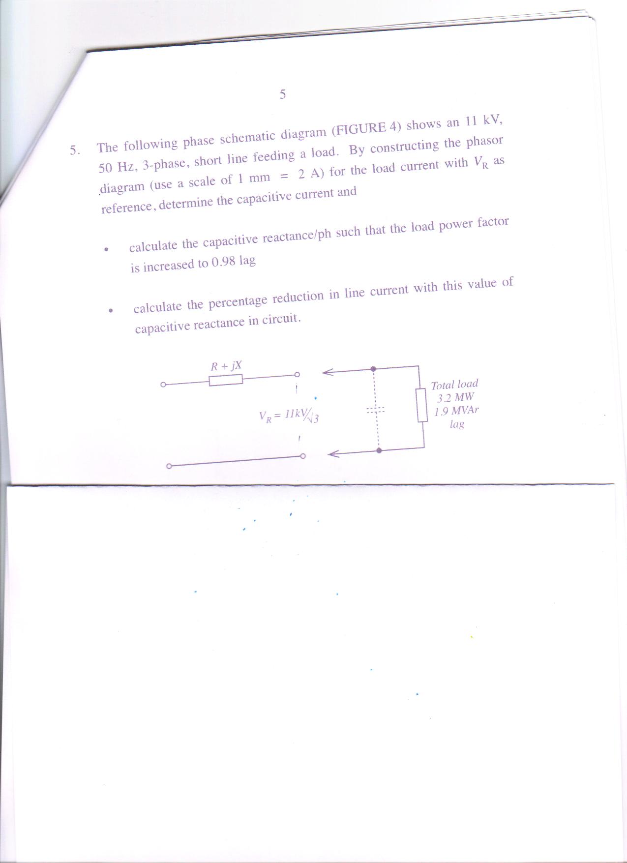
The phase schematic diagram in the attachment, shows an 11 kV, 50 Hz, 3-phase, short line feeding a load. By constructing the phasor diagram (use a scale of 1 mm = 2 A) for the load current with V_R as reference, determine the capacitive current and
* calculate the capacitive reactance/ph such that the load power factor is increased to 0.98 lag,
* calculate the percentage reduction in line current with this value of capacitive reactance in circuit.
Purchase this Solution
Solution Summary
This posting contains the solution to the given problems.
Solution Preview
Please see the attachment for the solution to the given problem.
The phasor diagram will be:
To achieve a 0.98 lag, the needed total reactive power is:
The reactive ...
Purchase this Solution
Free BrainMass Quizzes
Architectural History
This quiz is intended to test the basics of History of Architecture- foundation for all architectural courses.
Air Pollution Control - Environmental Science
Working principle of ESP