Power supplies regulated & unregulated problems and solutions
Not what you're looking for?
Please see attached
Purchase this Solution
Solution Summary
Power supplies regulated and unregulated problems and solutions are provided.
Solution Preview
Hello Neil
Please find attachment with solutions carried out in the relatively short time frame I had available, thanks
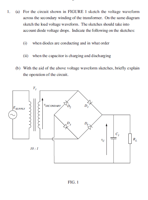
Operation during the positive half cycle (across the secondary)
When the secondary voltage at the transformer shows a positive cycle both diodes D_1 and D_3 are forward biased so conduct. Conventional current flows through D_1 the load and through D_3 back to the secondary coil as shown by the arrows. In such a state both diodes D_1,D_3 drop a voltage of ~ 0.7V each when conducting so by KVL we can write
V_SEC=0.7V+V_L+0.7V=V_L+1.4V
Thus the voltage across the load at any time during the positive half cycle is
V_L=V_SEC-1.4V
Operation during the negative half cycle (across the secondary)
When the secondary voltage at the transformer shows a negative cycle both diodes D_2 and D_4 are forward biased so conduct. Conventional current flows through D_4 the load and through D_2 back to the secondary coil as shown by the arrows. In such a state both diodes D_2,D_4 drop a voltage of ~ 0.7V each when conducting so by KVL we can write
V_SEC=0.7V+V_L+0.7V=V_L+1.4V
Thus the voltage across the load at any time during the positive half cycle is
V_L=V_SEC-1.4V
We note that current flows in the same direction through the load during both positive and
negative half cycles on the secondary occurring. Current effectively stops flowing when the
forward bias across diodes goes below 0.7V , this is when the secondary voltage is in the range
-0.7V≤V_SEC≤0.7V
The resultant waveforms are drawn below. Load voltage is positive for every half cycle whereas
the secondary voltage is pure sinusoidal. This is full wave rectification
The capacitor charges when the load resistor voltage is positive going and discharges during the period that the load resistors voltage is negative going as shown in the expanded view below
(a) Reference here
(i) The transformer is a 10:1 step down transformer so the rms voltage on the secondary coil is 1/10
the rms voltage specified for the primary (assuming ideal transformer behaviour)
Thus V_SEC (rms)=0.1×230=23V
Peak to peak voltage across secondary coil of the transformer is √2 the rms voltage so
V_SEC ...
Purchase this Solution
Free BrainMass Quizzes
Air Pollution Control - Environmental Science
Working principle of ESP
Architectural History
This quiz is intended to test the basics of History of Architecture- foundation for all architectural courses.