Purchase Solution
Working with basic emitter follower
Not what you're looking for?
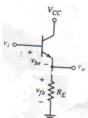
Derive the expressions for closed-loop gain Avf, input resistance Rif, and output resistance Rof of the following image.
Purchase this Solution
Solution Summary
The expert derives the expression for closed-loop gain Avf, input resistance Rif and output resistance Rof for an image. The solution helps with all explanations and mathematical steps.
Solution Preview
This is a schematic of the basic emitter follower circuit. Just a transistor and a single resistor from the emitter to ground.
Writing the voltage equation around the input loop,
Vi - Vbe - Vo = 0 ---------- 1
Making Vbe very small or the gain large, we have, Vi =(approx.) = Vo
The ...
Purchase this Solution
Free BrainMass Quizzes
Air Pollution Control - Environmental Science
Working principle of ESP
Architectural History
This quiz is intended to test the basics of History of Architecture- foundation for all architectural courses.