Question & solution around the trans impedance opamp circuit
Not what you're looking for?
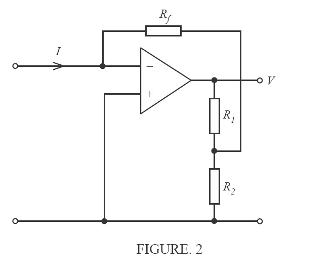
(a) The circuit of FIGURE 2 (attached) is known as a trans-impedance circuit used for the measurement of very small currents. Derive the relationship between the output voltage V and the input current I; i.e. if V = kI find k in terms of R1, R2 and Rf.
(b) Calculate the current I if Rf =10 mOhm (milli-Ohms), R1 = 90 kOhm, R2=10 kOhm, and V= 0.1 V.
Purchase this Solution
Solution Summary
A relationship is derived between the input current and the measured output voltage for the transimpedance Opsamp circuit in terms of the resistances R1, R2 and Rf. Values of R1 = 90 kOhm, R2 = 10 kOhm, Rf = 10 mOhm with Vout = 0.1V and the input current value is derived
Solution Preview
For the Ideal Op-Amp, the virtual earth theorem applies, meaning that the potential at both the + and - terminals is ~ 0 V. We can thus determine the potential at point A as that due to the potential divider formed by Rf parallel with R2 in turn in series with R1. So
R2 || Rf = R2*Rf/(R2 + Rf)
Hence by voltage divider ...
Purchase this Solution
Free BrainMass Quizzes
Introduction to Nanotechnology/Nanomaterials
This quiz is for any area of science. Test yourself to see what knowledge of nanotechnology you have. This content will also make you familiar with basic concepts of nanotechnology.
Intro to the Physics Waves
Some short-answer questions involving the basic vocabulary of string, sound, and water waves.
The Moon
Test your knowledge of moon phases and movement.
Variables in Science Experiments
How well do you understand variables? Test your knowledge of independent (manipulated), dependent (responding), and controlled variables with this 10 question quiz.
Classical Mechanics
This quiz is designed to test and improve your knowledge on Classical Mechanics.