Karnaugh Map reduction for D Type Asynchronous counter design
Not what you're looking for?
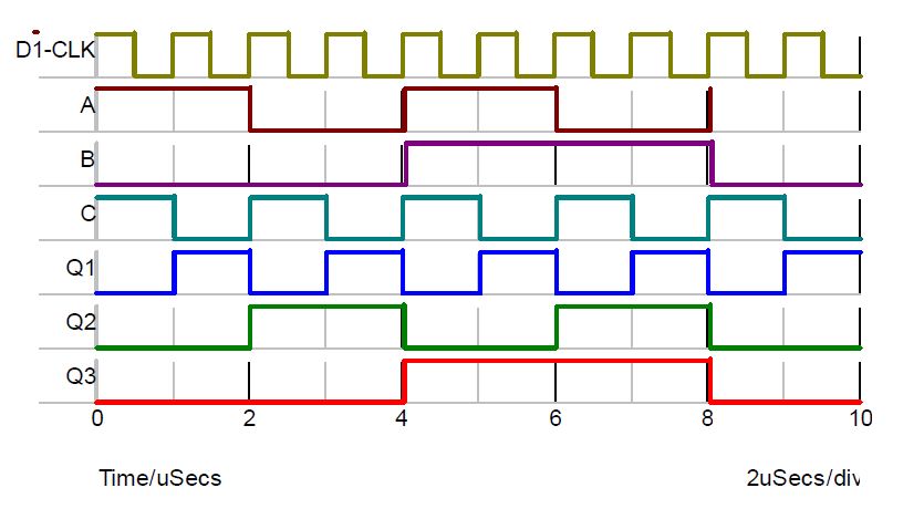
Q4 A three-stage type D counter circuit is required to produce the waveforms below (see Question4 attachment).
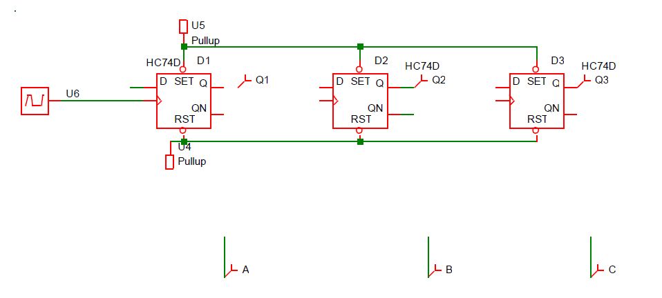
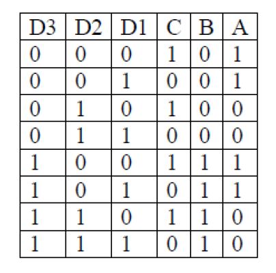
A skeletal form of the counter circuit is given in the PSpice schematic* (Question4PSpiceschematic attachment), along with the associated truth table (Question4TruthTable attachment). The outputs of the circuit are A, B and C and they are generated by the counter outputs Q1, Q2 and Q3.
a) Derive the relationship [a Boolean expression] between each output and the inputs [by, for example, plotting a Karnaugh map for each output].
Purchase this Solution
Solution Summary
Karnaugh Map Boolean logic reduction is used to derive minimized logic for an Asynchronous Counter built from D Type Flip Flops
Solution Preview
Please see attached solutions & guidance
I have drawn a Karnaugh map for output A. Note when drawing Karnaugh Maps you need to make sure that you label adjacent cells so that they only differ in changing one digit at a time, so for instance if you look at the vertical column axis for D1D2 it is labelled 00, 01, 11, 10 (note each cell in this sequence ...
Purchase this Solution
Free BrainMass Quizzes
Air Pollution Control - Environmental Science
Working principle of ESP
Architectural History
This quiz is intended to test the basics of History of Architecture- foundation for all architectural courses.