Full Wave Center Tap Bridge Rectifier
Not what you're looking for?
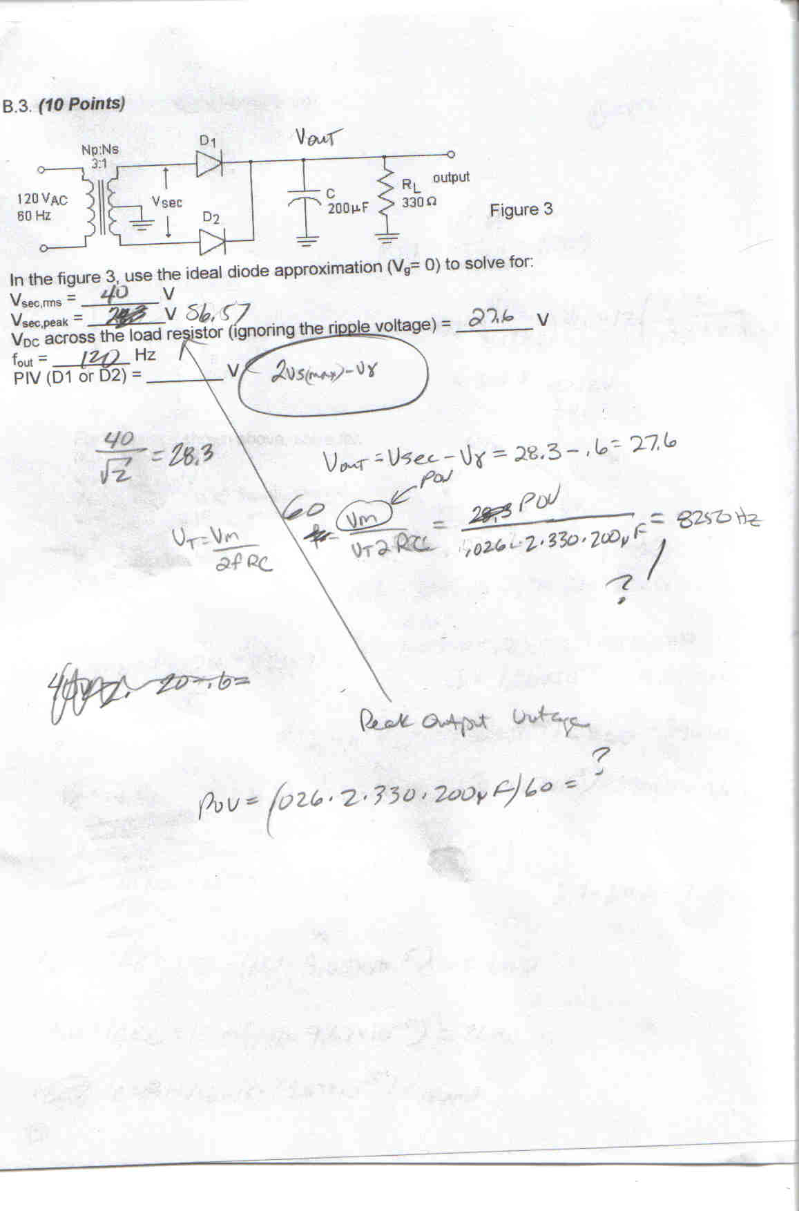
In the attached image, how is VDC across the load resistor found?
The practice test has an answer of 28.24 ignoring the ripple voltage. VDC across the resister is Vout right? So, Vsecondary - the voltage drop in the diode = Vout = VDC
So, if the secondary winding has 40voltage - .7V drop in the top resistor, that's 39.3V. How is 28.24 derived? Thank you.
Also, when asked for the power dissipated in the transistor, exactly which voltage and current is used in the calculation? Is it Ve and ie?
What is a varacter operated in the reverse saturation region? Is seems like the depletion region width is being controlled by a variable forward bias - why is this wrong?
Thank you.
Please answer all 3 questions.
Purchase this Solution
Solution Summary
This solution provides an explanation for finding Voltage using transform factor and reference to diodes and capacitors.
Solution Preview
Hi,
The Transform factor is 3:1 so the output will be 120/3=40V "rms". If one wants to find the V peak to peak at the left he must multiply with 2 times sqrt[2] - 2 times because his wave goes from -Vp to +Vp (sine wave with negative and positive values).At the right of the T/F you we have Vp-p=2*sqrt[2]*40Vrms - Attention: That is at the coil from top to bottom! If you count from Top to the middle or from Middle to bottom it is 20 Vrms - so be careful
We take as reference the ground, which is the middle of the coil! After the Diodes all of the negatives has become positives we have ...
Purchase this Solution
Free BrainMass Quizzes
Air Pollution Control - Environmental Science
Working principle of ESP
Architectural History
This quiz is intended to test the basics of History of Architecture- foundation for all architectural courses.