Magnetically Coupled Autotransformer
Not what you're looking for?
Please show as much working as possible and comment where possible.
Please refer to attached diagrams for complete questions and mentioned figures.
1. The diagram below shows an autotransformer represented as two separate inductors, L1 and L2, magnetically coupled with a coupling coefficient k.
a) Apply Kirchhoff's voltage law to the input and output circuits (to loops ABC and DBC) to obtain equations for V1 and V2.
b) Show that the open-circuit (I2 = 0) voltage ratio is given by:
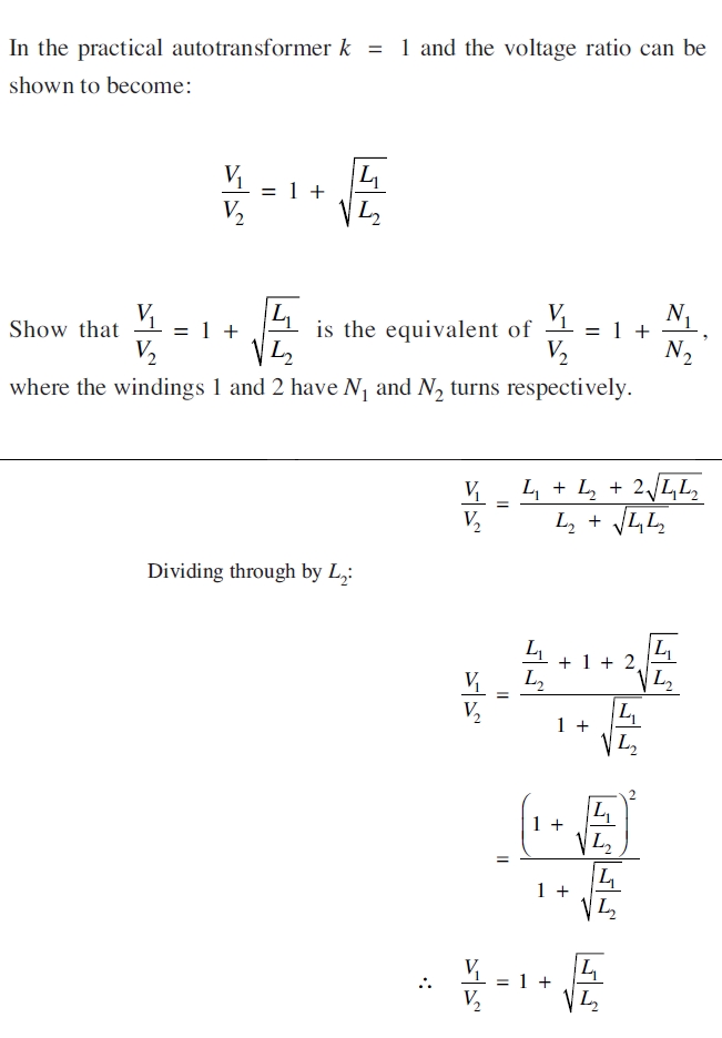
2. In the practical autotransformer k=1 and the voltage ratio can be shown to become:
V1/V2 = 1 + SQRT(L1/L2)
Show that V1/V2 = 1 + SQRT(L1/L2) is the equivalent of V1/V2 = 1 + (N1/N2), where the windings 1 and 2 have N1 and N2 turns respectively.
Purchase this Solution
Solution Summary
This posting contains the solution to the given problems.
Purchase this Solution
Free BrainMass Quizzes
Introduction to Nanotechnology/Nanomaterials
This quiz is for any area of science. Test yourself to see what knowledge of nanotechnology you have. This content will also make you familiar with basic concepts of nanotechnology.
The Moon
Test your knowledge of moon phases and movement.
Classical Mechanics
This quiz is designed to test and improve your knowledge on Classical Mechanics.
Basic Physics
This quiz will test your knowledge about basic Physics.
Variables in Science Experiments
How well do you understand variables? Test your knowledge of independent (manipulated), dependent (responding), and controlled variables with this 10 question quiz.