NEXT and FEXT crosstalk calculations
Not what you're looking for?
For a lossless line:
The characteristic impedance is given by Zo=sqrt(L/C) and the velocity of propagation by Vp=1/(sqrt(L*C))
Where L and C are, respectively, the line's inductance and capacitance per metre length.
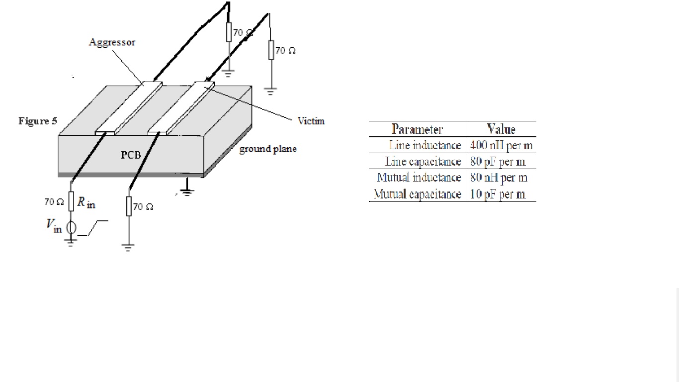
A transmission line is formed by two identical parallel tracks in a printed circuit board, as depicted in the attached figure. The line has a length of 50 mm and all line terminations are of 70 . The line can be assumed to be lossless.
a) Use equations (1) and (2) to calculate the magnitude of the NEXT and FEXT voltages generated in the victim conductor when the source voltage, Vin, in the aggressor conductor is a voltage step of 2 V with a rise time of 100 ps.
[Note that the Vs voltage at the input to the aggressor conductor is
Vs=Vin(Rin/Rin+Zo)]. Please see attached drawing.
Equations:
NEXT
The crosstalk voltage appearing at the near end of the victim circuit due to a changing voltage Vs(t) in the aggressor circuit is given by:
Vne=Kne[Vs(t)-Vs(t-2td)]............(1a)
Kne=1/4td(C*Zo+L/Zo)...............(1b)
Kne is the near end coupling coefficient and C and L are the per unit length mutual capacitance and inductance respectively and td is the time taken for the aggressor signal to travel down the line.
FEXT
The crosstalk voltage generated at the far end of the victim circuit due to a changing voltage Vs(t) in the aggressor circuit is given by:
Vfe=Kfe*l*d/dt[Vs(t-td)]...............(2a)
where l is the length of the line
Kfe=1/2(C*Zo-L/Zo.....................(2b)
b) Sketch the NEXT and FEXT waveforms.
Purchase this Solution
Solution Summary
The expert examines NEXT and FEXT crosstalk calculations.
Solution Preview
Please see the 2 attachments for the solution.
- Near End Cross Talk NEXT voltage analysis
The NEXT voltage is given by 1a.
1a.
where is given by 1b.
1b.
However, since the characteristic impedance of the transmission line is given by the square root of the ratio of unit length line inductance and unit length line capacitance we can write and the velocity of propagation of signals along the line given by which on substitution into 1b yields the alternative simplified form for given by equation1c as shown below.
1c.
We can evaluate these ratios since we are given the unit length mutual inductance between the lines as and the unit length line inductance as so
In addition as we are given the unit length mutual capacitance between the lines as and the unit length line capacitance as so we can evaluate the ratio
Then
Also we need to evaluate using the parameter values given where
Then
Since
And
We can also work out the velocity ...
Purchase this Solution
Free BrainMass Quizzes
Architectural History
This quiz is intended to test the basics of History of Architecture- foundation for all architectural courses.
Air Pollution Control - Environmental Science
Working principle of ESP