Logic design involves turning abstract circuit behavior, most often register transfer level, into meaningful implementation via logic gates. This conversion of a circuit's functional design to a representation that can work with logic operators (OR, AND, XOR, NAND, NOT), control flow, and many other important tasks is a standard step in the design cycle of a computer's hardware. This builds the foundations on which more complicated operations, like arithmetic ones (+, -, etc.) can be performed. This area of hardware design shoes that, in essence, circuits are simply complex binary operations that we can implement via the basic aforementioned logical operators.
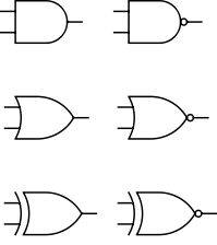
Logic gate examples, from left to right, top to bottom: AND, NAND, OR, NOR, XOR, and a comporator)
The first step is logic design, then circuit design. In today's world, the logic design step may even be left to the control of a machine, using whichever high-level synthesis tools are appropriate for the circuit's intended behavior. These tools' techniques differ, but common methods and tricks include:
- synthesizing HDLs (VHDL and Verilog included)
- generating bitstreams for programmable logic devices
- creating ASICs
Most commonly, the output of this aspect of electronic design automation is register-transfer-level description. While far from being an accessible programming languages, this is one of the early steps toward moving from a simple flow of current to a fully-programmable computer and so should not be taken for granted.
© BrainMass Inc. brainmass.com April 24, 2024, 6:50 am ad1c9bdddf